

CELLGUARD™ Wireless-EN
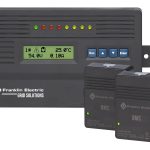
The CELLGUARD™ Wireless Battery Monitoring System (BMS) provides an accurate and reliable indication of battery state-of-health through monitoring and analysis of battery voltage, temperature, and conductance.
- Mô tả
Mô tả
SPECIFICATIONS
BASE COORDINATOR UNIT (BCU)
Specifications
| Component | Specification |
| Battery Strings | 1-16 |
| Batteries per String | 1-300 |
| Battery Voltage Test Interval Range | 1 – 24 hrs |
| Battery Conductance Test Interval Range | 1 – 30 days |
| Power Input | 9-12VDC @ 800mA |
| Operating Temperature | 0°C – 65°C |
| Storage Temperature | -10°C – 80°C |
| Processor | Quad Core @ 1250MHz |
| RAM | 1Gb SDRAM @ 400Mhz |
| Storage | 4GB micro SD card |
| 4 X USB Type A | 2.0 |
| UART | Baud Rate: 57.6Kbps; Data Bits: 8; Parity Bit: None; Stop Bit: 1 |
| Ethernet | RJ45; 10/100Mbps; Auto-Negotiate; 802.3 Compliant |
| Analog Alarm Input | 0.2-10 V differential |
| Binary Alarm Input | Dry Contact |
| Major/Minor Alarm Output | Form C Relay 110 VDC 125 VAC max |
| Wireless RF Radio Band | 802.15.4 compliant; 2.4 GHz @ 8mW (6.3dBm) |
| Modbus | Ethernet TCP/IP UDP |
| Regulatory Compliance | FCC, CE, RoHS, IEEE |
| Physical Dimensions | L:7.80in, W:4.47in, H:1.44in |
Capabilities
- Supports up to 16 strings with 300 batteries per string
- Supports up to 600 sensors per BCU (irrespective of how they are divided by strings)
- Examples of BCU String Configurations:
- If 60 cells per string, then the max is 10 strings (60 x 10 = 600)
- If 4 batteries per string, then the max is 16 strings (4 x 16 = 64)
- If 24 cells per string, then the max is 16 strings (24 x 16 = 384)
- If 240 cells per string, then the max is 2 strings (240 x 2 = 480)
- Network communications
- DNP3 Communications
- Embedded Internal Web Server
- Field upgradable software
- Two ambient temperature sensors
- String voltage capture (Sum of Batteries)
- Discharge data collection and reporting
- Remote network configuration
- Field hardware commissioning
- External Alarm Dry Contacts – Utilized with ELS System
- Capture string and battery data, reports to CELLTRAQ™ Battery Management Software at scheduled frequency
WIRELESS BATTERY SENSOR
Specifications
| Component | Specification |
| Wireless RF Radio Band | 802.15.4 compliant; 2.4 GHz @ 8mW (6.3dBm) |
| Wireless RF Range | 0 – 30m |
| Operating Temperature | 0°C – 65°C |
| Storage Temperature | -10°C – 80°C |
| Test Current Draw | 1100 – 4500 mA depending on Battery Float Voltage |
| Regulatory Compliance | FCC, CE, RoHS, IEEE |
| Voltage Resolution | 1mV |
| Conductance Resolution | 1℧ |
| Physical Dimensions | 2.63in L, 2.64 in W, 1.06 in H |
Capabilities
- One sensor per cell/jar
- 2V, 6V, 8V, 12V
- Sensors capture voltage, temperature, & conductance
- Strap Resistance monitoring
- Mesh routing communication
- Quick, fully hot swappable sensor and/or wiring harness
- Field upgradable firmware
- Compatible with VRLA and VLA batteries
- Patented conductance technology
- Non-Invasive to the battery
- Accurate battery state-of-health results
- Wireless system, minimizes wiring, installation costs & maintenance
Measurement & Accuracy
| VOLTAGE | CONDUCTANCE | TEMP @ NEGATIVE POST | RESISTANCE | IDLE CURRENT | |||||
| Model | Measured Range |
Accuracy | Meas. Range Per Cell |
Accuracy | Measured Range |
Accuracy | Measured Range |
Accuracy | Measured Range |
| CGS3-02V M(XX) | 1.75 – 2.50 VDC | +/- 20mV | 100 – 15,000 ℧ | +/- 3% | -10°C – +65°C | +/- 2°C | N/A | N/A | 70 – 80mA |
| CGS3-12V M(XX) | 10.50 – 15.0 VDC | +/- 20mV | 100 – 4,200 ℧ | +/- 3% | -10°C – +65°C | +/- 2°C | N/A | N/A | 50 – 60mA |
| CGS3-100-2V | 1.75 – 2.50 VDC | +/- 20mV | 100 – 15,000 ℧ | +/- 3% | -10°C – +65°C | +/- 2°C | 2 – 1,000 μΩ | +/- 20 μΩ | 70 – 80mA |
| CGS3-100-06V-12V | 6.50 – 14.50VDC | +/- 20mV | 100 – 4,200 ℧ | +/- 3% | -10°C – +65°C | +/- 2°C | 2 – 1,000 μΩ | +/- 20 μΩ | 50 – 60mA |
VOLTAGE, TEMPERATURE, CURRENT (VTC) UNIT
Specifications
| Component | Specification |
| Wireless RF Radio Band | 802.15.4 compliant; 2.4 GHz @ 8mW (6.3dBm) |
| Operating Temperature | 0°C – 65°C |
| Storage Temperature | -10°C – 80°C |
| Regulatory Compliance | FCC, CE, RoHS, IEEE |
| Voltage Resolution | 1mV |
| Physical Dimensions | L:4.00in, W:2.50in, H:1.09in |
| Wireless RF range | 0 – 30m |
| Resolution | 1A |
Capabilities
- String current & ripple current monitoring
- Measurements include voltage, current, ripple current, and temperature
- Compatible with battery string configurations commonly found in telecommunications, power utility, and UPS applications between 18-480VDC nominal
- Powered by the battery string, eliminating the need for an external power source
Measurement & Accuracy
| Model | Voltage Input | Accuracy | Current Range | Accuracy of Current Input |
Discharge Current |
Ripple Current Accuracy |
| CGVTC2-60 | 20 – 70 VDC | +/- 3% | 5 – 200 A | +/- 3% +/- 2A | -5 – -400 A | 3% |
| CGVTC2-300 | 90 – 300 VDC | +/- 3% | 5 – 200 A | +/- 3% +/- 2A | -5 – -400 A | 3% |
| CGVTC2-600 | 300 – 600 VDC | +/- 3% | 5 – 200 A | +/- 3% +/- 2A | -5 – -400 A | 3% |
BCU AC WALL WART POWER ADAPTER
Specifications
| Component | Specification |
| Input Voltage Rating | 100 – 240 Vac, 50 – 60 Hz |
| Output Voltage | 9 Vdc |
| Output Current | 0.8A |
| No Load Power (stand by) | <100mW |
| Power Efficiency | >80.01% |
| Temperature Range | 0 to +40° C at full load |
| ETL | 60950 1 |
| EMI standard | FCC part 15 class B |
Capabilities
- Over voltage and short circuit protected
TELCO DC-DC CONVERTER
Specifications
| Component | Specification |
| Input Voltage Range | 24 – 65 Vdc |
| Output Voltage | 12 Vdc +/-1% Load Regulation |
| Output Power | 10 Watts Max |
| Isolation Voltage | Input to output for 1 minute 1500 Vac |
| Power Efficiency | 86% Typical |
| Temperature Range | -40 to 85° C |
| Safety and Protections | Fused String Power Cable assembly |
| Dimensions | 3.972 in L x .876 in H x 0.6 in W |
UTILITY/UPS DC-DC CONVERTER
Specifications
| Component | Specification |
| Input Voltage Range | 100~1000 Vdc |
| Output Voltage | 12 Vdc |
| Output Power | 10 Watts Max |
| Isolation Voltage | Input to output for 1 minute 4000 Vac |
| Power Efficiency | 77% Typical |
| Operating Temperature | -40 to 70° C |
| Safety and Protections | Fused String Power Cable assembly |
| Dimensions | 3.783 in L x 2.126 in Hx 1.441 in W |
SOLID CORE CURRENT TRANSDUCER
Specifications
- Solid-Core Closed Loop Hall Effect current sensor
| Component | Specification |
| Overall accuracy at 25C | 0.5% |
| Primary through hole | 1.57 in (40 mm) diameter |
SPLIT CORE CURRENT TRANSDUCER
Specifications
- Split-Core Closed Loop Hall Effect current sensor
| Component | Specification |
| Overall accuracy at 25C | 2.5% |
| Primary through hole | 4.09 in x 1.57” (104 mm x 40 mm) |


